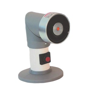
Electromagnets Range F
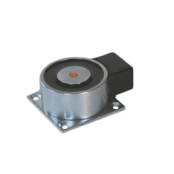
Electromagnets with connection terminal on the mounting plate
Characteristics
- Range formed by electromagnets EM GD 40, EM GD 50, EM GD 60 and EM GD 70
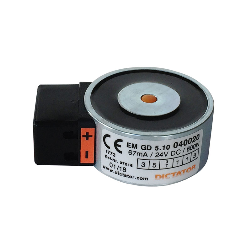
- Connection terminal on the mounting plate of the magnet
- Magnet and base plate of zinc-plated steel as standard
- Equipped with a spark extinction diode as standard: in case of faulty connection, the integrated polarity protection prevents the spark extinction diode from being destroyed
- As counter piece for the electromagnet, a counter plate has to be fixed on the door
- All electromagnets with ‘LE 07016’ in their description have been tested according to EN 11557
- Some articles may differ from the photo

Product details
Technical data
| Voltage | 24 VDC +/-10 % |
| Temperature range | -20 °C to +60 °C |
| Surface | zinc-plated steel |
| Remanence | 0 N |
| Duty cycle | 100 % |
| Holding force EM GD 40 | 300 N |
| Holding force EM GD 50 | 600 N |
| Holding force EM GD 60 | 700 N |
| Holding force EM GD 60 S | 1000 N |
| Holding force EM GD 70 | 1450 N |
| Holding force EM GD 70 S | 1700 N |
| Holding force EM GD 70 R | 2000 N |
| Power consumption EM GD 40 | 75 mA (1.8 W) |
| Power consumption EM GD 50/EM GD 60 | 67 mA (1.6 W) |
| Power consumption EM GD 60 S | 79 mA (1.9 W) |
| Power consumption EM GD 70 | 71 mA (1.7 W) |
| Power consumption EM GD 70 S/EM GD 70 R | 142 mA (3.4 W) |
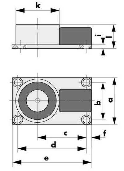
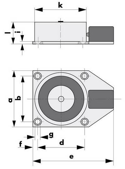
Dimensions
All dimensions in mm
Dimensions of EM GD 40 F23 and EM GD 50 F 26 magnets
| Typ / Type / Tipo | a | b | c | d | e | f | g | i | k | l |
|---|---|---|---|---|---|---|---|---|---|---|
| EM GD 40 F 23 | 45 | 35 | 45 | 63 | 73 | 5 | ø 4,5 | 3 | ø 40 | 23 |
| EM GD 50 F 26 | 55 | 44 | 51 | 74 | 83 | 4,5 | ø 4,5 | 3 | ø 50 | 26 |
Dimensions of EM GD 60 F26 and EM GD 70 F 39 magnets
| Typ / Type / Tipo | a | b | d | e | f | g | i | k | l |
|---|---|---|---|---|---|---|---|---|---|
| EM GD 60 F 26 | 65 | 55 | 55 | 93 | 5 | ø 4,5 | 3 | ø 60 | 26 |
| EM GD 70 F 39 | 75 | 60 | 60 | 103 | 7,5 | ø 5,5 | 4 | ø 70 | 39 |
Installation
Installation notes
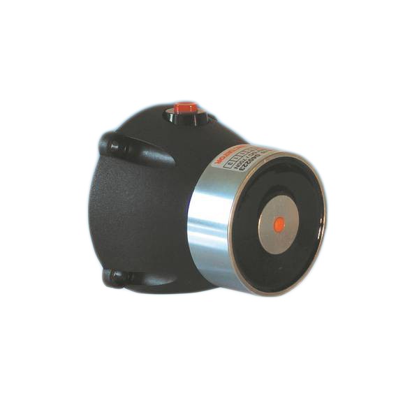
The F-range electromagnets have a connection terminal that is fixed to the mounting plate of the magnet. For the electrical connection, simply pull off the black cap and then snap it on again.
Installation instructions
Order information
Order Information
| Description | Part No. |
|---|---|
| EM GD 70 F 39 R electromagnet, 2000 N, 24 VDC | 040122 |
| EM GD 70 F 39 S electromagnet, 1700 N, 24 VDC | 040115 |
| EM GD 70 F 39 electromagnet, 1450 N, 24 VDC, LE 07016 | 040037 |
| EM GD 60 F 26 S electromagnet, 1000 N, 24 VDC, LE 070016 | 040163 |
| EM GD 60 F 26 electromagnet, 700 N, 24 VDC, LE 07016 | 040049 |
| EM GD 50 F 26 electromagnet, 600 N, 24 VDC, LE 07016 | 040106 |
| EM GD 40 F 23 electromagnet, 300 N, 24 VDC | 040085 |
Downloads
| File Name | Type |
|---|---|
| Documents | |
| Catalog: Electromagnets | |
| Data sheet - Electromagnets range F | |
| Installation Instructions Electromagnets | |
| DWG Drawings | |
| DWG EM GD 60 F 26, 040049 | dwg |
| DWG EM GD 60 F 26 S, 040163 | dwg |
| DWG EM GD 70 F 39, 040037 | dwg |
| DWG EM GD 70 F 39 S, 040115 | dwg |
| DWG EM GD 70 F 39 R, 040122 | dwg |
| STEP Drawings | |
| STEP Electromagnet EMGD 60 F26, 040049 | stp |
| STEP Electromagnet EMGD 60 F26S, 040163 | stp |
| STEP Electromagnet EMGD 70 F39, 040037 | stp |
| STEP Electromagnet EMGD 70 F39S, 040115 | stp |