Electromagnets range Q
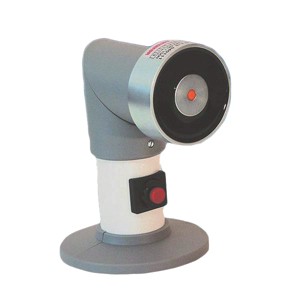
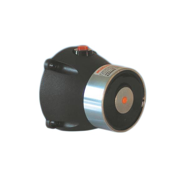
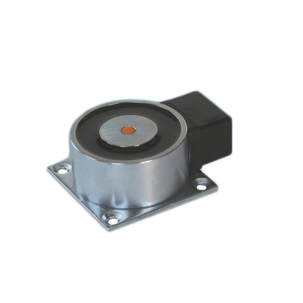
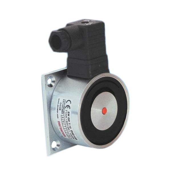
Electromagnets with lateral connection terminal
Characteristics
- Electromagnets with no fixing plate
- The body of the magnet has an M6 threaded hole in its back for adjusting the magnet individually to each installation situation
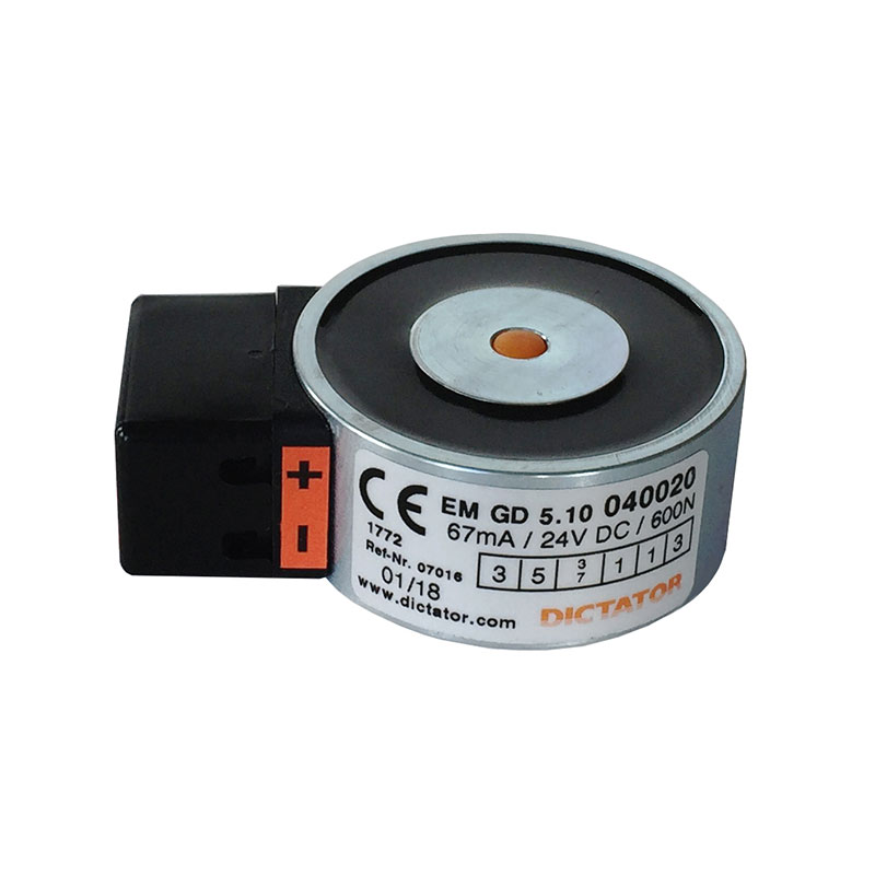
- Lateral connection terminal for an easy connection
- Made of zinc-plated steel
- Equipped with a spark extinction diode as standard: in case of faulty connection, the integrated polarity protection prevents the spark extinction diode from being destroyed
- As counter piece for the electromagnet, a counter plate has to be fixed on the door
- All electromagnets with ‘LE 07016’ in their description have been tested according to EN 1155
- Some articles may differ from the photo
Product details
Technical data
| Voltage | 24 VDC +/-10 % |
| Protection | IP 20 |
| Temperature range | -20 °C to +60 °C |
| Surface | zinc-plated steel |
| Remanence | 0 N |
| Duty cycle | 100 % |
| Holding force EM GD 50 | 600 N |
| Holding force EM GD 70 | 1450 N |
| Power consumption EM GD 50 | 67 mA (1.6 W) |
| Power consumption EM GD 70 | 71 mA (1.7 W) |
Dimensions
All dimensions in mm
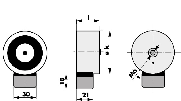
| Typ / Type / Tipo | k | l | t |
|---|---|---|---|
| EM GD 50 Q 23 | ø 50 | 23 | 10 |
| EM GD 70 Q 35 | ø 70 | 35 | 15 |
Installation
Installation notes
The magnets of the Q range are not intended for being fixed directly to a wall. They are fixed with a screw from behind. For this purpose there is a M6 threaded hole in the back of the magnet body.
They are connected electrically in the connection terminal fixed laterally to the magnet.
Installation instructions
Order information
Order Information
| Description | Part No. |
|---|---|
| EM GD 70 Q 35 electromagnet, 1450 N, 24 VDC, LE 07016 | 040022 |
| EM GD 50 Q 23 electromagnet, 600 N, 24 VDC, LE 07016 | 040020 |
Downloads
| File name | Type |
|---|---|
| Documents | |
| Catalog: Electromagnets | |
| Data sheet - Electromagnets range Q | |
| Installation Instructions Electromagnets | |
| DWG Drawings | |
| DWG EM GD 50 Q 23, 040020 | dwg |
| DWG EM GD 70 Q 35, 040022 | dwg |
| STEP Drawings | |
| STEP Electromagnet EMGD 50 Q23, 040020 | stp |
| STEP EMGD 70 Q 35, 040022 | stp |