Damping diagrams
Lamellar radial dampers LD
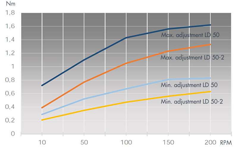
- The following two diagrams show the damping force of the LD 50 and LD 100 series of lamellar radial dampers.
- Both series differ only in their height. The base dimensions are identical.
- They offers a very large adjusting range.
- There are two damping ranges shown in the diagram for the LD 50. They are determined by the type of oil used.
- Other damping ranges are also possible on request.
Radial damper LD 50 / LD 50-2
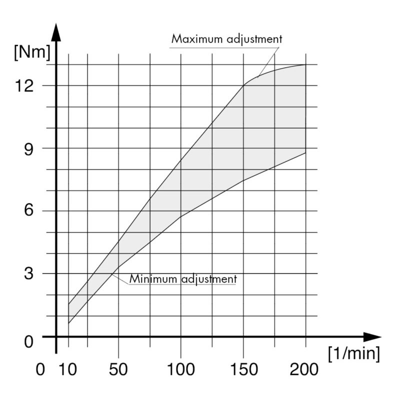
Radial damper LD 100
Notes about the diagrams
The values shown in the diagram were determined in a standardized test environment. The two factors here were:
- Installation of the lamellar radial damper vertically, adjustment screw points downwards
- Ambient temperature 22 – 25 °C
When the damper is used in actuality, the damping behavior can additionally be influenced by various external factors, so that the damping behavior in actual use may deviate from that shown in the diagram.
The lamellar dampers are not intended for continuous operation because they may overheat, which has a negative effect on its durability. The temperature of the damper, which is influenced by ambient temperature, actuation frequency, speed and the settings of the control (damping power), should preferably not exceed 50°C on the outside of the housing.
Radial dampers series RD 240/241
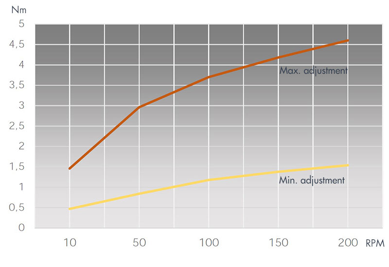
- The damping forces of the RD 240/241 series can be seen in the two following diagrams.
- Most of the RD 240/241 models have been tested for use on fire sliding doors.
- The case of this series is made of aluminium. Therefore they allow a slightly higher duty cycle than the lamellar radial dampers LD.
- You can find more detailed information about the different standard models under Series RD 240/241
- Upon request there are other models available
Radial damper 240 – 241
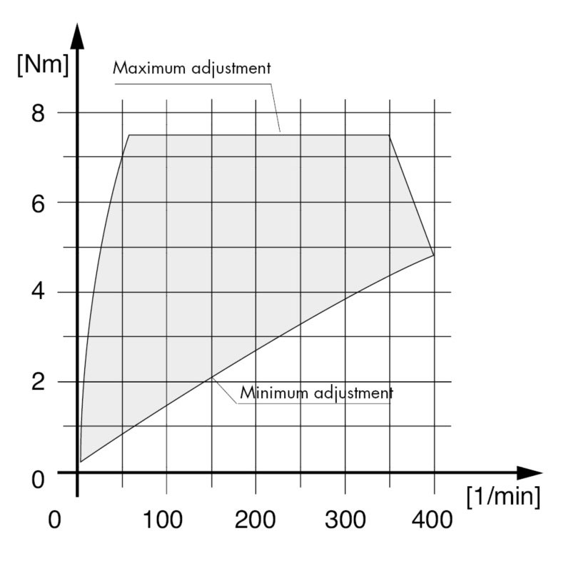
Radial damper 241024 – 241030