Electromagnets range S
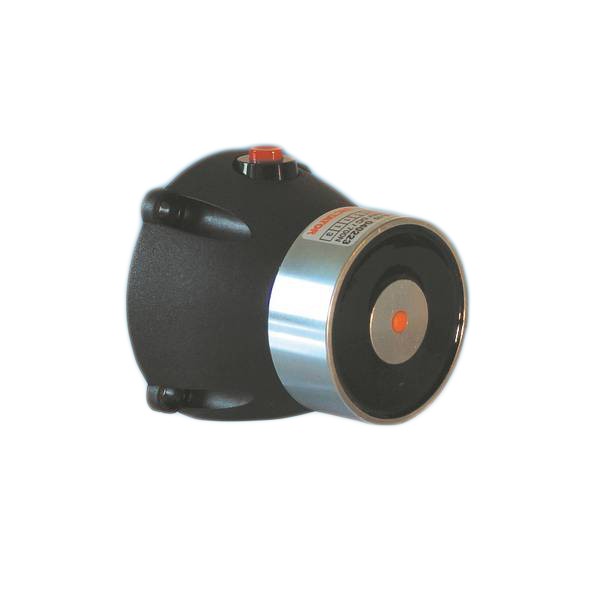
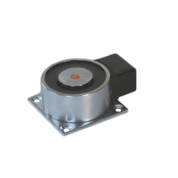
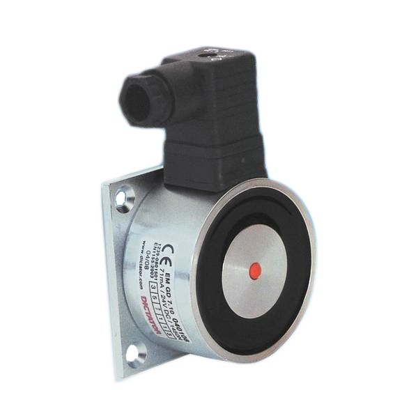
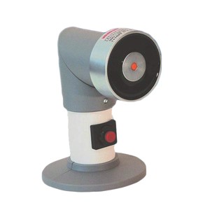
Electromagnets with swivel head, for floor, wall or ceiling installation
Characteristics
- Can be used for many applications, as its head can be rotated
- Head position can be adjusted to the correct position without interfering with any electrical connections
- Distance tube allows to compensate distance differences between wall/ceiling/floor and door
- Tube available in three different lengths and can also be shortened on site to the required length if necessary
- Interruptor key integrated in the distance tube. If well-accessible, an additional hand release switch is not needed
- Electromagnet with 175 mm distance tube also available without interruptor key, in which case a separate release switch is necessary
- Mounting plate and distance tube in lacquered steel (RAL 9010 pure white), magnet itself of zinc-plated steel, other parts of dust grey plastic (RAL 7037)
- Equipped with a spark extinction diode as standard: in case of faulty connection, the integrated polarity protection prevents the spark extinction diode from being destroyed
- As counter piece for the electromagnet, a counter plate has to be fixed on the door
- All electromagnets with ‘LE 07016’ in their description have been tested according to EN 1155
- Some articles may differ from the photo
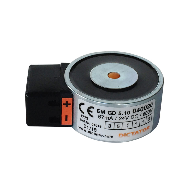
Product details
Technical data
| Voltage | 24 VDC +/-10 % |
| Protection | IP 40 |
| Temperature range | -20 °C to +60 °C |
| Surface | zinc-plated; powder coated RAL 9010 |
| Remanence | 0 N |
| Duty cycle | 100 % |
| Holding force EM GD 60 | 700 N |
| Holding force EM GD 60 S | 1000 N |
| Power consumption EM GD 60 | 67 mA (1.6 W) |
| Power consumption EM GD 60 S | 79 mA (1.9 W) |
Dimensions
All dimensions in mm
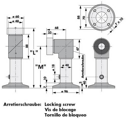
| Typ | Länge 'L' | Höhe 'M' | Bestell-Nr. |
|---|---|---|---|
| EM GD 60 S 175 | 175 | 107 | 040111 |
| EM GD 60 S 175 S | 175 | 107 | 040164 |
| EM GD 60 S 325 | 325 | 257 | 040112 |
| EM GD 60 S 475 | 475 | 407 | 040113 |
Installation
 Installation notes
The electromagnet with swivel head can be fixed to the floor, ceiling or wall behind the open door.
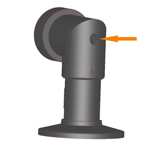
If you want to change the position of the head, the locking screw need to be loosened (see picture) and the head needs to be turned 90º (for floor or ceiling installation). Afterwards the locking screw must be tightened again.
For cutting the distance tube, remove the head after loosening both grub screws which fix the head to the tube. Then pull out the wires connected to the interrupter key. The connection wires are inserted through an opening in the mounting plate. After the magnet has been properly installed and wired, both plastic covers have to be pushed from the side over the mounting plate and clipped into position.
Installation instructions
Order information
Order Information
| Description | Part No. |
|---|---|
| EM GD 60 S 175 electromagnet, 700 N, 24 VDC, LE 07016 | 040111 |
| EM GD 60 S 175 S electromagnet, 1000 N, 24 VDC, LE 07016 | 040164 |
| EM GD 60 S 175 oT electromagnet, 700 N, 24 VDC, LE 07016 | 040264 |
| EM GD 60 S 325 electromagnet, 700 N, 24 VDC, LE 07016 | 040112 |
| EM GD 60 S 475 electromagnet, 700 N, 24 VDC, LE 07016 | 040113 |